TM 10-1670-268-20&P 0016 00
0016 00-4
(2) Reposition the replacement eyebolts aligning them vertically with the mast.
(3) Secure the eyebolt to the mast by once again routing a pry bar through the eyebolt and
tighten the nut with a 9/16-inch wrench or socket.
c. Replace Link Knob.
(1) Replace a damaged knob by simply unscrewing the knob from the link and screwing on a
serviceable knob in its place.
d. Quick Release Pin Lanyard Assembly.
(1) Should the quick release pin lanyard fray or separate from the quick release pin, remove the
lanyard from the mast using a 5/32-inch allen wrench and remove the cap head screw.
(2) Obtain a serviceable quick release pin with lanyard and attach to the mast handle mast using
a 5/32-inch allen wrench and re-installing the cap head screw.
INSTALL
1. Install the link on each side of the aft end of the platform as follows:
a. If applicable, remove (pry out) the two black plastic hole plugs in the rear panel, closest to the
panel joint line, and the two black hole plugs in the adjacent panel, closest to the panel joint line.
Push out, through these holes, the four black plastic plugs on the opposite surface. Save these
plugs for use in remaining panels as required.
CAUTION
Use of a pry-bar should not be necessary during the initial assembly
of the dual row platform. If using a pry bar to install the PFA link on
an assembled platform, exercise extreme caution to avoid bowing
the side rail.
b. Using a ¾-inch wrench or socket, remove side rail bolts (numbers 31-36), washers and spacers.
c. Slide each link into the groove between the platform rail and the platform panel end fitting. Use a
pry-bar if necessary to open the groove as the link is inserted.
d. Slide link forward until its bolt-holes are matched up with platform clevis bolt-holes 31 through 34.
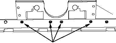
BOLT HOLES 31-34