ARMY TM 10-1670-279-23&P
AIR FORCE T.O. 13C5-27-2
NAVY NAVAIR 13-1-28
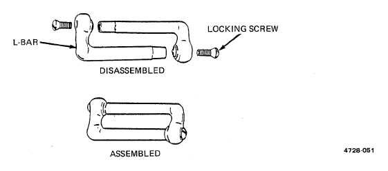
Figure 2-51. Connector Link Assembly.
(3)
As applicable, position an L-bar of replacement link assembly adjacent to disassembled
original link assembly and slide suspension lines from damaged link onto replacement link.
(4)
If required, pass remaining L-bar of replacement link through attaching loop of adjoining
component.
(5)
Fit replacement link L-bars together and ensure L-bar leg engagement by tapping end of
each L-bar with a mallet.
(6)
As applicable, trace suspension lines from connector link assembly to canopy to ensure
lines are properly installed and in correct sequence.
2-91