
TM 10-1670-327-23&P
0007 00
2
3
1
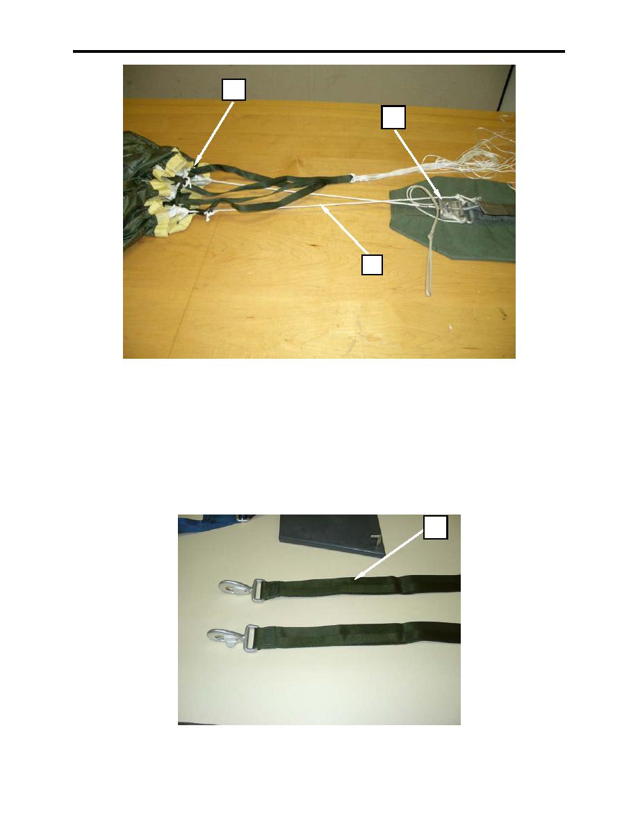
Figure 4. Attaching Reserve Risers To Reserve Canopy.
4. At the lower lateral band, split the canopy between the left and right line groups.
5. Layout the reserve risers (figure 5, item 1) directly behind the connector link groups ensuring there
are no twists.
6. Evenly mate the hook pile tape between the reserve risers plies.
7. Ensure the gates of the snap hooks are facing downwards and the butterfly portions of the snap hooks
are facing outwards.
1
Figure 5. Laying Out Risers.
0007 00-4

