
TM 10-1670-327-23&P
0015 00
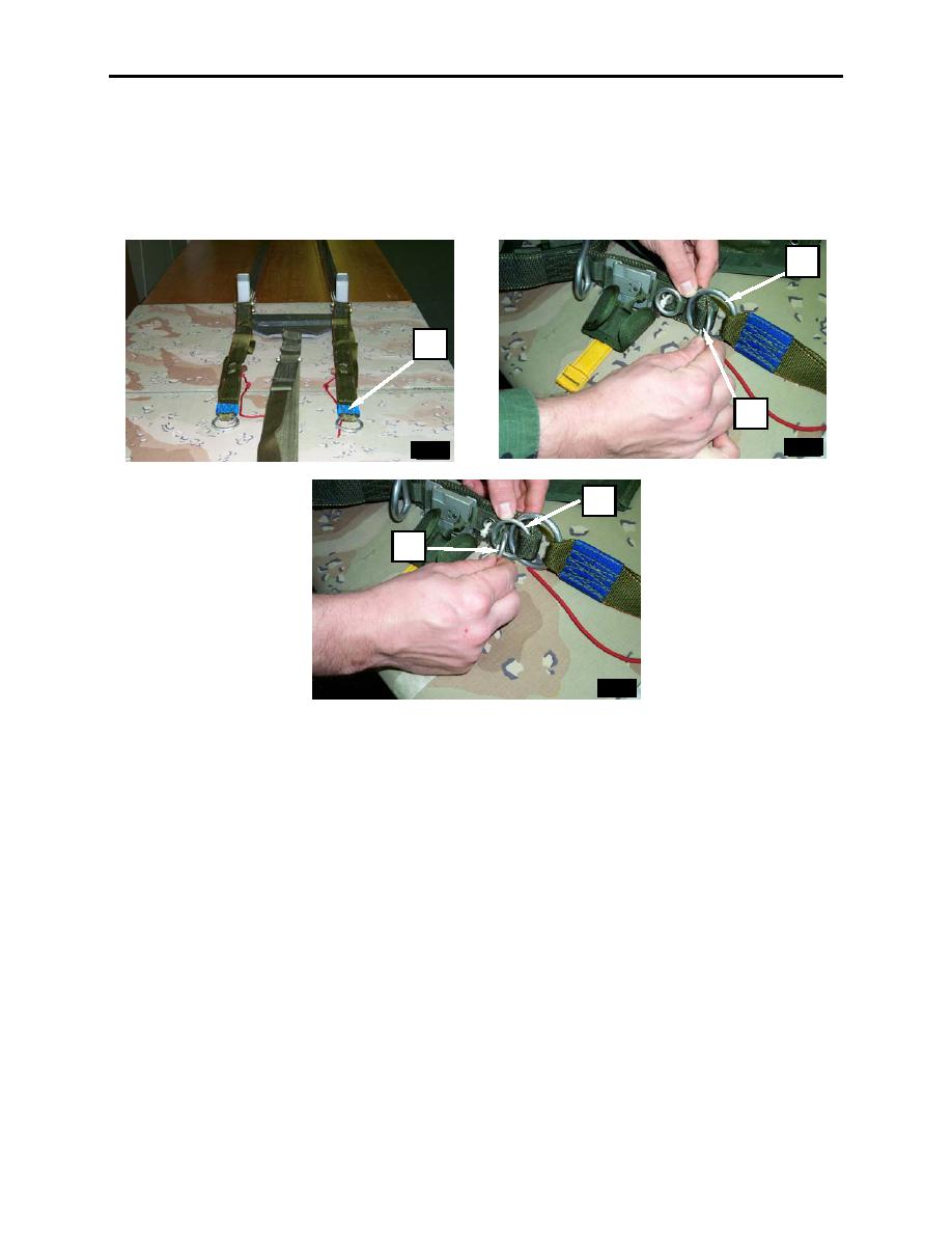
4. Ensure risers and harness are free of tangles and twists and lay out harness with smooth side up.
Make certain risers are identified with a blue confluence wrap on each riser (figure 13, item 1).
5. Route large ring of upper main lift web (figure 13, item 2) through large riser ring (figure 13, item 3).
6. Rotate the large ring of the upper main lift web (figure 13, item 4) up 180 and insert small ring
(figure 13, item 5) through large ring of upper main lift web (figure 13, item 4).
3
1
2
4
5
Figure 13. Laying Out Risers with Smooth Side Up, Routing Large Ring of Upper Main Lift Web through
Large Riser Ring, Rotating Large Ring of Upper Main Lift Web.
7. Pass the locking loop lug and soft loop (figure 14, item 1) through the small ring (figure 14, item 2)
and insert the lug (figure 14, item 3) into the jaws of the riser release (figure 14, item 4) by
depressing the two operating lug release levers (figure 14, item 5).
8. Ensure that the lug is fully seated into canopy release assembly (figure 14, item 6).
9. Close canopy release cover (figure 14, item 7), locking the loop (figure 14, item 8) in place.
0015 00-12

