
TM 10-1670-327-23&P
0030 00
REPLACE continued
4. Carefully remove stitching on the damaged extended gore assembly. Take note on how the extended
gore is attached. Clean the area by removing all loose pieces of thread.
NOTE
There is some overlap of the reinforcement tapes on the forward and aft extended gores.
You may need to remove some of the stitching of the aft extended gore. This stitching
must be replaced when the new forward extended gore is sewn into place.
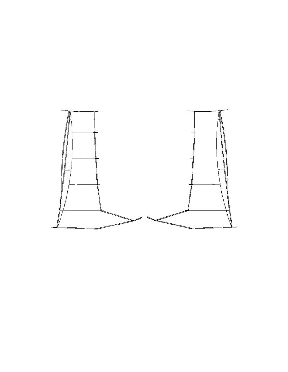
5. Take a new aft extended gore (figure 1). Ensure that you have the correct assembly; left extended
gore assembly for the jumpers left side; right extended gore assembly for the jumpers right side.
Left
Right
Forward
Forward
Aft Edge
Aft Edge
Edge
Edge
Figure 1. Identifying a Left and Right Extended Gore Assembly.
0030 00-2

