
TM 10-1670-327-23&P
0032 00
REPLACE - continued
Position Control Lines on Main Parachute. After replacing a lower control line, position control lines as
follows:
1
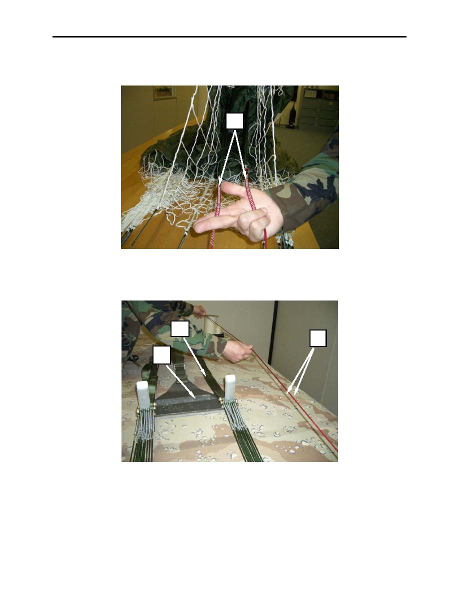
Figure 2. Ensuring Lower Control Lines are Free and Clear.
1. Trace the lower control lines (left and right) (figure 3, item 1) down to the risers end (figure 3, item
2) ensure that the lower control lines are free and clear from suspension lines and are routed to the
outside of the tension bar (figure 3, item 3).
2
1
3
Figure 3. Tracing Lower Control Lines Down To Risers.
NOTE
Requires two rigger personnel to conduct measurement.
2. Measure the lower control lines (left and right) under 5 lbs of pressure.
3. Using a calibrated scale, insert the scale hook-end (figure 4, item 1) into the girth hitch (figure 4,
item 2) where the lower control line (figure 4, item 3) is attached to the middle control line cascade.
0032 00-3

