
TM 10-1670-327-23&P
0032 00
REPLACE - continued
1
2
3
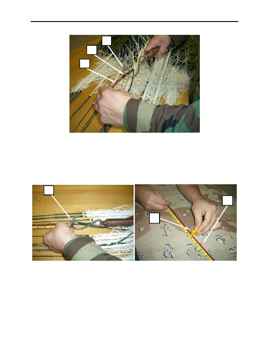
Figure 4. Inserting Scale Hook-end into Girth Hitch.
NOTE
Ensure that ruler and line are lying flat on the packing table and outside of the tension
device.
4. Measure from where the lower control line (figure 5, item 1) is girth hitched to the middle control line
cascade down to the riser end and mark the control line at 282 inch (figure 5, item 2) with a yellow
mark. Follow procedure for both lower control lines.
1
1
2
Figure 5. Marking Control Line at 282 Inches.
5. Once the measurements are completed, route both lower control lines (left and right) to the center of
both left and right suspension line groups, ensure the lower control lines are free and clear and to the
inside of the suspension line groups.
6. Pass each lower control line (figure 6, item 1) through the two control line channels (located on the
inside of each rear riser) (figure 6, item 2), then through the guide ring (figure 6, item 3) and finally
through the wooden toggle (figure 6, item 4).
0032 00-4

