
TM 10-1670-327-23&P
0069 00
REPLACE - continued
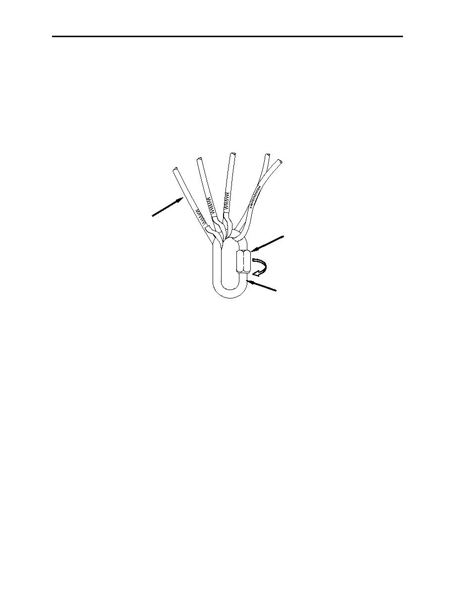
2. Using an 8-inch adjustable wrench, loosen barrel nuts (figure 2, item 1) on connector links (figure 2,
item 2) and remove risers.
3. Remove suspension lines (figure 2, item 3) from connector links (figure 2, item 2) and discard
unserviceable links.
4. Position replacement links so that barrels face inboard and tighten downward. Attach suspension
lines to their corresponding connector links without crossing.
3
1
2
Figure 2. Replacing Connector Links.
5. Install risers (figure 3, item 1) onto applicable connector links (figure 3, item 2).
6. Using an 8-inch adjustable wrench, tighten barrel nuts (figure 3, item 3) on connector links (figure 3,
item 2) hand tight plus 1/4-turn.
7. Hand tack (figure 3, item 4) each riser at connector link (figure 3, item 2) with one turn double, tape,
lacing and tying utilizing the procedures in WP 0007 00.
0069 00-2

