ARMY TM 10-1670-275-23&P
AIR FORCE TO 13C5-25-2
NAVY NAVAIR 13-1-26
4706-021
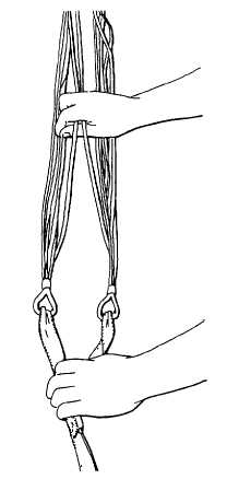
Figure 2-14. Removing Twists.
h. Proper Layout.
(1) Locate top center gore of canopy and divide suspension lines into two groups. Lines 1 thru 7 should
be in left group, lines 8 thru 14 in right group, lines 1 and 14 should be located on top of their
respective group, lines 7 and 8 on bottom (figure 2-15)
(2) Place a packing weight around right group of lines to maintain separation between line groups (figure
2-15).
(3) Check canopy assembly for proper layout by raising top and bottom center gores, and tracing
suspension lines to connector loops. Check lines 1, 14, 7 and 8 for proper position (figure 2-15).
2-29