ARMY TM 10-1670-281-23&P
AIR FORCE T.O. 13CS32-2
NAVY NAVAIR 13-1-32
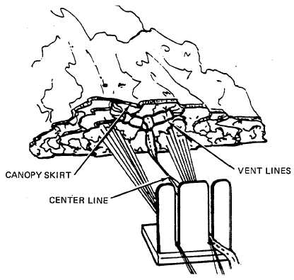
(e) Rigger 1 stops pulling on the center line when the served portion of the canopy vent lines becomes
alined with the canopy skirt (figure 2-68).
4839-063
Figure 2-68. Canopy Vent Lines Alined with Canopy Skirt .
(f )
Riggers 2 and 3 lay the top center gore back down on the canopy, insuring that the gore is
dressed along the lower edge and each side.
(g)
Place the center line on top of the right suspension line group. The running end loop of the
center line should be located 6 to 9 inches below the 3/4-inch clevis.
(h)
Remove tension device from clevis.
(i)
Remove nut and screw from clevis.
(j)
Remove one of the risers from the clevis.
(k)
Install center line running end loop on clevis.
(l)
Replace riser and assemble the screw and nut on the clevis (figure 2-69).
2-77