TM 10-1670-292-23&P 0028 00
0028 00-3
d. Lock the stitching ends by ½-inch. Stitching will be made using a medium-duty sewing machine
and size E, nylon thread (Tables 1 and 2, WP 0012 00).
e. Position the stitched tape lengthwise on the riser in the original channel location or according to
the details illustrated above, as applicable.
f.
Form the control line channel by securing the tape to the riser with a single row of stitching made
1/8-inch along each long edge of the tape. Overstitch each end of the tape by ¼-inch. The
stitching will be made using the specifics in Table 2, WP 0012 00.
REPLACE
Replace an unserviceable riser assembly as follows:
1. Remove the old risers by removing the screws and disassembling the link assemblies.
2. Obtain a serviceable riser assembly from stock.
3. When replacing a riser assembly, make certain the risers are not twisted and that, when the male
canopy release fitting is facing down, the suspension lines are in proper sequence and location on the
connector links.
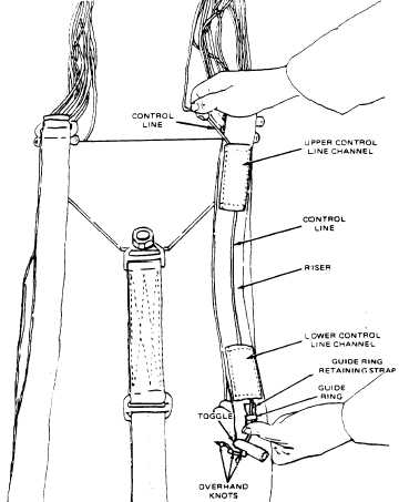
4. Check the toggle attachment and trace the bottom end of the control line as illustrated below.