TM 10-1670-296-20&P 0020 00
0020 00-4
c.
Clean housing cover with brush.
d.
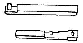
Insert the short key onto the timer actuator pin, into its slot with its pin facing outward.
e.
Insert the longest key into its slot, also with its pin facing outward.
f.
Adjust the two installed keys so that their pins are aligned with the pin in the housing and install the
toggle over all three pins.
g.
Check to see that the short key is properly located onto the timer’s spring-located actuator pin (6)
and that the toggle is located onto all three pins in line.
h.
Replace housing cover over keys with countersunk holes facing outward and rounded comers along
outer edge of timer housing. Check for alignment of holes and install four screws carefully. Do not
over-tighten screws.
i.
Turn timer stem ¼ turn to right and check if keys extend from each side of housing. Release stem
and allow the timer to run down, making sure that the keys retract at the end when the timer runs
down.
NOTE
The interlock pin must be down before the timer can be armed.
4. Reassemble release.
NOTE
The faceplate bolts for the M-1 Cargo Parachute Release are the
correct type and length when they come with the complete assembly.
However, many spare part bolts available are different when you
requisition them. A spare part bolt of the same material with the correct
length is identified by bolt, NSN 5306-00-207-8362, part number, AN6-
25A. However, an additional bolt has been sold and may be used until
exhausted. This bolt is NSN 5306-00-638-5821, Part Number AN6H-
25A. This substitute bolt is the correct length and size, but it has a hole
drilled in the head for specific aircraft applications. This bolt is
acceptable for use in the assembly and application of the M-1 cargo
parachute release.