TM 10-1670-296-20&P 0047 00
0047 00-2
REPAIR
Repair Defective LED(s).
1. Set the POWER switch on the control box and 28 VDC power supply to OFF. Disconnect power cable
from the control box.
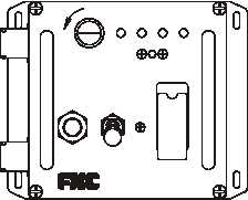
2. Remove the four screws and the cover of the control box.
3. On the backside of the cover, using nut driver, remove the two nuts holding the printed circuit board
(PCB) to the cover. Carefully remove the PCB from the cover.
4. Remove and discard the defective LED(s) from its socket.
LAMP
SWITCH
JETTISON
1
POWER
OFF
ON
NUMBER OF LOADS
DIMMER
DIM
TEST
FLAT
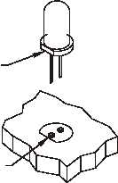
INSTALL LED SO FLAT
COINCIDES WITH FLAT
SILKSCREENED ON PCB
CAUTION
Make sure that the flat on the flange of the LED lines up with the flat that
is marked on the PCB. Improper installation may damage the LED.
5. Install the new LED(s) so the flat side of the LED base matches the flat side of circle on PCB.
6. Reinstall the PCB to the cover using the two (2) nuts.
7. Reinstall the cover of the control box using the four (4) screws.
8. Repeat the inspection procedure to ensure all LEDs light up.
REPLACE
Replace an unserviceable control box with a serviceable item from stock.
END OF WORK PACKAGE


