ARMY TM 10-1670-271-23&P
AIR FORCE TO 14D1-2-464-2
MARINE CORPS TM 01136B-23&P/1
2-29. Suspension Line (CONT).
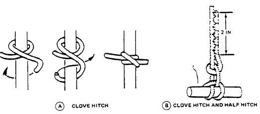
(7) Relieve tension on all lines and attach new suspension line to link assembly with a clove hitch and
half hitch (see figure 2-96).
Figure 2-96. Clove Hitch and Half Hitch.
(8) The procedures above may be reversed by drawing new line down through V-tab, attaching new line
to link assembly, then to the canopy skirt.
(9) Extend each tie running and toward the canopy skirt and beginning at a point 2 inches above the
knots made In step (7), secure each tie running end to the replacement canopy line body by stitching
a 3/16-inch-wide by 2-inch-long double-throw zig-zag stitch formation toward the connector link
assembly. Finish each stitch formation as close as possible to the securing knots and trim each
running end to 1/4 inch. Use nylon thread, size E and 7 to 11 stitches per inch
(10) Compare the knots securing each end of the replacement canopy line with the adjacent knots made
on the connector link assembly to ensure compatibility. In addition, trace each end of the
replacement line from the connector link assembly to the canopy skirt to ensure proper attachment,
position, and sequence.
(11) Restitch anti-inversion net to suspension line using a zig-zag sewing machine, size E nylon thread,
7 to 11 stitches per inch.
Change 2
2-132