ARMY TM 10-1670-271-23&P
AIR FORCE TO 14D1-2-464-2
MARINE CORPS TM 01136B-23&P/1
2-34. Pack Tray (CONT).
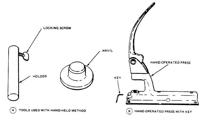
Figure 2-126. Snap fastener Installation Tools.
3 Using the specifics in Appendix B, ascertain the size die and chuck required for installing the fastener
cap and socket or stud and post, as applicable.
4 Place the selected chuck in the open end of the holder and secure the chuck in place using the
locking screw located on one side of the holder. Place the; appropriate die into the anvil.
5 Fit the socket or stud, as applicable, on the chuck lower end (figure 2-127). Place the cap or post, as
applicable, on the die with the barrel facing up.
6 Position the material over the barrel of the cap or post. Ensure that the fastener socket or stud will be
located on the proper side of the material for subsequent fastener engagement.
7 Place the socket or stud, on the barrel of the cap or post. With an applied strike from a mallet, clinch
the two snap fastener components to the material.
8 Remove the clinched snap fastener components from the chuck and die set and check the seating of
the joined components. If the applicable components are not properly seated, repeat the procedure
in step 7 above.
2-168