TM 10-1670-286-20
EXTRACTION LINE PANEL PROCEDURES FOR C-17 GLOBEMASTER III 0016 00
STOWING THE 140-FOOT THREE LOOP EXTRACTION LINE TO THE EXTRACTION
LINE PANEL WITH EXTRACTION BRIDLE ATTACHED
0016 00-11
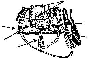
Figure 14. 22’ Extraction Parachute Secured to
Extraction Line Bag.
8. Install Lanyard and Safety Ties.
NOTE
Install Deployment Bag Figure Eight Safety Tie IAW WP 0012 00.
a. Cut a 60-inch length of ½-inch tubular nylon used as a parachute deployment bag cutter knife
lanyard.
CAUTION
The cutter knife lanyard must be adjusted to ensure it is 2 inches shorter than
the parachute adapter web, measure from the point where the adapter web
exists the parachute deployment bag at the figure eight tie, to where the
adapter web attaches to the two-point link.
b. Using a 3 ¾-inch two-point link, connect the parachute adapter web to the extraction line. Fold the
½-inch tubular nylon in half and girth-hitch through the cutter knife. Extend lanyard and attach to the
middle of the top plate of the two-point link.
c. Secure ends of tie with three alternating half hitches and an overhand knot in running ends. Trim
off excess and tape (figure 15).
d. Tape the bolts of the ¾-inch 2-point link using a suitable length of 2-inch pressure sensitive
adhesive tape.
Strap Handle
(Bottom Panel)
V-Ring
Tie
Deployment Bag
Bottom Securing Loop
Canopy Breakcord Tie
Parachute Attaching Webs