TM 10-1670-272-23&P 0011 00
0011 00-14
(2) Remove twists from one group at a time by rotating risers until lines are in proper location on
the connector links.
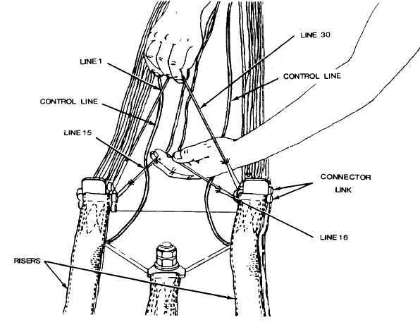
4. Check the suspension lines for proper layout. Left group should have line 1 on the top inside of the
connector link and line 15 on the bottom inside of the connector link. The right group will have line 30
on the top inside of the connector link and line 16 on the bottom inside of the connector link. Ensure
the control lines are routed to the inside of the risers and are not routed around any of the suspension
lines.
5. Assemble parachute components in accordance with Assembling the MC1-1B/MC1-1E Parachute
(WP 0004 00).