TM 10-1670-293-23&P
0035 00
0035 00-2
6. Hold the adjacent line and the new line tightly together at the lower lateral band; trace both lines, from
the canopy skirt to the link assembly, under equal tension. Mark the new line at a point even with the
inside edge of the link. Apply equal tension to both lines and check correctness of marking.
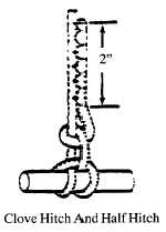
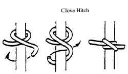
7. Relieve tension on all lines and attach the new suspension line to the link assembly with a clove hitch
and a half hitch.
8. Drawing the new line down through the V-tab may reverse the procedures above; attach the new line to
the link assembly, then to the canopy skirt.
9. Extend each tie running end toward the canopy skirt and, beginning at a point 2-inches above the knots
made in step 7., secure each tie running end to the replacement canopy line body by stitching a 3/16-
inch-wide by 2-inch-long double-throw, zig-zag stitch formation toward the connector link assembly.
Finish each stitch formation as close as possible to the securing knots and trim each running end to ¼-
inch. Use size E, nylon thread, and 7 to 11 stitches per inch.
10. Compare the knots securing each end of the replacement canopy line with the adjacent knots made on
the connector link assembly to ensure compatibility. In addition, trace each end of the replacement line
from the connector link assembly to the canopy skirt to ensure proper attachment, position, and
sequence.
END OF WORK PACKAGE