ARMY TM 10-1670-294-23&P
AIR FORCE T.O. 13C5-33-2
NAVY NAVAIR 13-1-34
2-16. Packing the 35-Foot Cargo Parachute (cont).
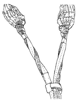
Figure 2-13. Removing Twists.
h.
Proper Layout.
(1)
Locate top center gore of canopy and divide suspension lines into two groups. Lines 1 thru 24 should
be In right group, lines 25 thru 48 in left group, lines 1 and 48 should be located on top outside of their
respective groups, lines 24 and 25 on the bottom inside (figure 2-14).
(2)
Check canopy assembly for proper layout by raising top and bottom center gores, and tracing
suspension' lines to connector links. Check lines 1, 48, 24 and 25 for proper position(figure 2-14).
i. Assembling Components
NOTE
When the parachute Is received from the supply activity and before it is packed for
use, the components must be assembled. This must be accomplished during the
layout of parachute (para 2-16c) after removing inversion, turns, tangles or twists,
If required. In assembling components, If any component is found to be defective,
parachute must be processed for repair. Place components on the packing lane
and obtain proper layout of canopy assembly; then assemble components in
accordance with the following:
(1)
Attaching deployment bag.
(a)
Pass the bridle loop of the canopy through the opening In the center of the deployment bag.
2-28