TM 9-1370-201-12
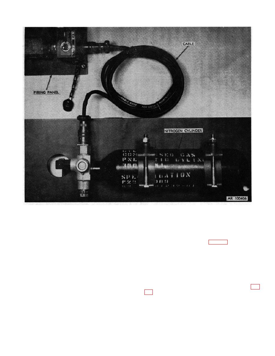
Figure 2-7. Cable connected to firing panel and nitrogen cylinder
firing device and turn safety switch to ARM position.
Depress handle of firing device by exerting firm, quick
c. Installation of Dispenser Assembly.
pressure, and observe flashing of lamp through test set
window. Flashing of lamp indicates that total electrical
(1) Assure that the two interlocks of the
circuitry is functioning. If lamp does not flash, a
jettison assembly are unlocked (figs. 1-6 and 17).
component or the test set is defective.
(2) Check rollers on underside of dispenser
assembly to make sure that they rotate freely.
NOTE
(3) Roll unloaded dispenser assembly onto
Window of test set should be held
track plate. Snout (retracted) must be at rightside
near eye when checking firing panel.
opening of helicopter.
It improves ability of operator to see
(4) Roll dispenser assembly back to
lamp flashing even in bright sunlight.
mechanical stop.
(5) Verify that vibration snubber screw (fig.
(3) After completion of test, place safety
switch in SAFE position, close cover, and rotate bail
(6) Manually engage retaining pins by
back to locked position under handle of firing device.
moving interlock handles towards rail.
(4) Remove test set and reconnect cable to
(7) Turn vibration snubber screw clockwise
firing panel.
2-8


