
TM 9-1370-202-12
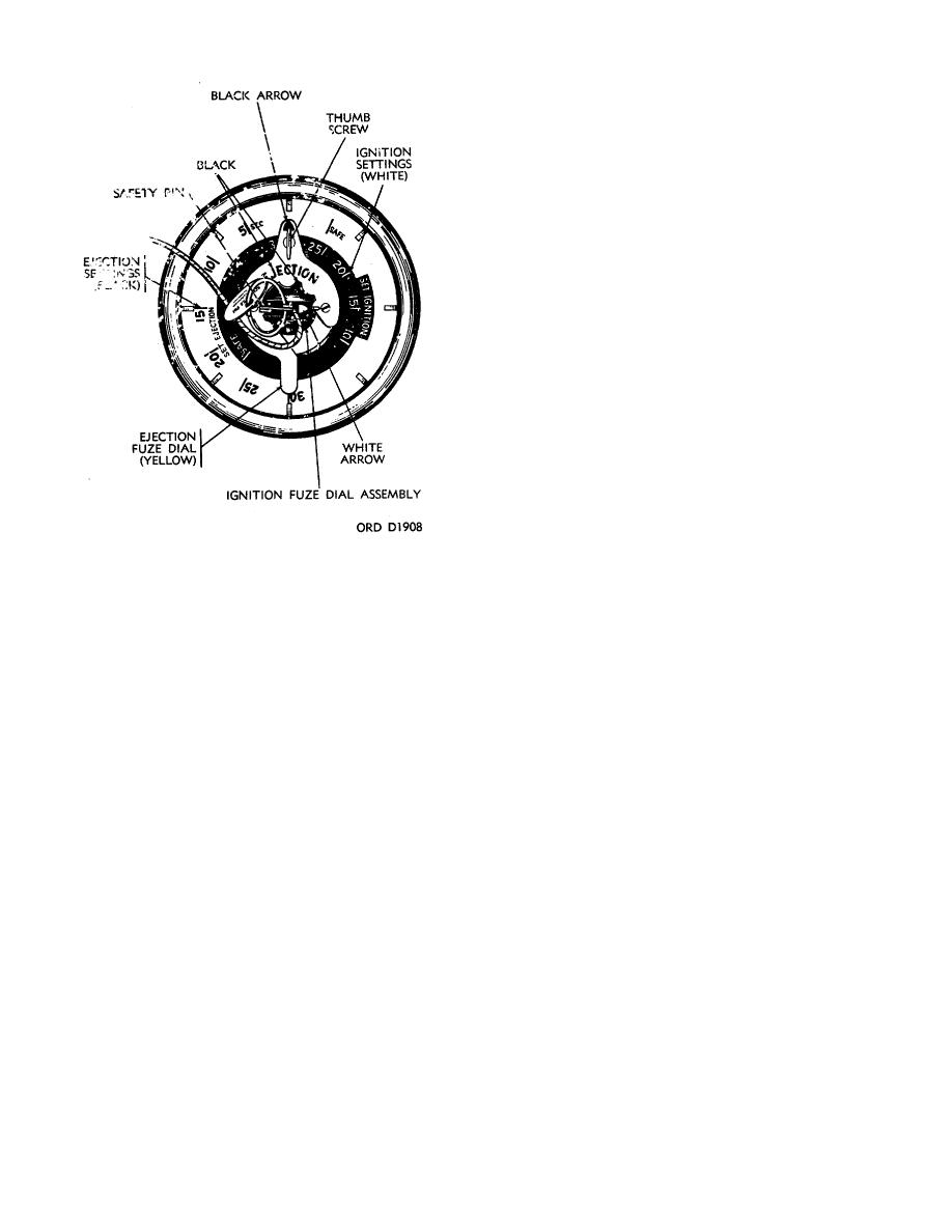
dial is yellow, with a red arrow which points to the outer
ring of black figures on the fuze dial.
(2) On all lots of Mod 3 produced after March,
1966, the ejection fuze setting dial is yellow, with a black
arrow which points to the outer ring of black figures on
the fuze dial.
(3) On Mod 4, the ejection fuze setting dial is
stamped out of flat metal and is painted yellow, with a
black arrow which points to the outer ring of black
figures on the fuze dial. This dial is shaped more like a
pointer than the ejection fuze setting dials on Mods 1, 2,
2A and 3.
(4) On Mods 1, 2, 2A, and all lots of Mod 3
produced prior to March, 1966, a thumbscrew, which
locks the ejection and ignition dials during shipment and
storage, passes through the ejection and ignition fuze
setting dials. Mod 4 contains a thumbscrew which
passes through the yellow ejection fuze setting dial.
(5) Certain portions of the ejection fuze dial
on Mods 1, 2 and 2A are raised and can be gripped by
the fingers for fuze setting.
f. An ignition fuze assembly, which controls candle
Figure 3-4. Aircraft parachute flare Mh24, mod 4.
ignition, is located directly below the ejection fuze. It
consists of an ignition plunger and housing assembly, a
a. An outer case, consisting of a one-piece
delay fuse, and an ignition composition assembly.
aluminum tube, houses the complete flare and fuze
assembly. In Mod 1, the case is approximately 11/2
(1) In Mods 1 and 2, ignition fuze settings range
inches shorter than the flare and the plastic fuze
from 5 to 30 seconds in 5-second intervals.
extends beyond the end of the outer case. In all other
models, the fuze is contained within the case.
In all other models, the range is 10 to 30 seconds in 5-
second intervals.
b. A plastic weather cap, which protects the fuze
area during shipment and storage, is taped over the
(2) On Mods 1, 2, 2A and all lots of Mod 3 produced
fuzed end of the outer case.
prior to March, 1966, the ignition fuze setting dial is gray
(or black), with a white arrow which points to the inner
c. A desiccant bag, which protects the fuze
ring of white figures on the fuze dial.
assemblies from moisture during storage, is located
under the weather cap.
(3) On all lots of Mod 3 produced after March,
1966, and on Mod 4, the ignition fuze setting dial points
d. A lanyard assembly, coiled under the weather
to an inner ring of white figures on a black background
cap, consists of two flexible, stainless steel cables. The
on the fuze dial.
cables, respectively 7 and 27 inches long, are joined by
a disconnect.
(4) In Mods 1 and 2, there is no safety pin on the
fuze setting dials. However, in Mods 1, 2, 2A and all
e. An ejection fuze assembly, which controls
lots of Mod 3 produced prior to March, 1966, a
candle and parachute ejection from the outer case, is
thumbscrew, which locks the dials during shipment and
located directly below the fuze dials. It consists of an
storage, passes through the fuze setting dials. On Mods
ejection plunger and housing assembly, a delay fuse,
2A and 3, a safety cotter pin inserted through the
and an ejection composition assembly.
ignition dial stem prevents the lanyard from being
accidentally pulled and igniting
(1) On Mods 1, 2, 2A and all lots of Mod 3
produced prior to March, 1966, the ejection fuze setting
3-4
