ARMY TM 10-1670-282-23&P
AIR FORCE TO. 13CS30-2
NAVY NAVAIR 13-1-33
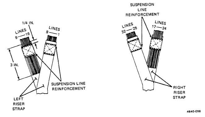
Figure 2-56. Suspension Line Arrangement on Riser Straps.
(2)
Right riserstrap. Replace a right riser strap using the procedures in paragraph (1), above. However, details
for attaching the parachute inspection data pocket (log record pocket) do not apply to the right riser strap. In addition, only
the riser identification markings will be stenciled on the right riser strap. The stenciling will be performed according to
original stenciling details, using the procedures in paragraph 2-19.
(3)
Spreader bar.
(a)
Cut and remove the stitching which secures the spreader bar webbing around each of the riser straps.
Remove the spreader bar from the riser assembly by cutting the spreader bar webbing.
(b)
Cut a 27-inch length of type VI nylon webbing and sear the ends.
(c)
Using a suitable marking aid, mark the webbing length at a point 8 1/2 inches from each end.
(d)
Center the webbing length between the riser straps in the original spreader bar location.
(e) Pass the left webbing end around the left riser strap and a line the webbing end with the mark made in (c)
above.
(f)
Secure the formed spreader bar end loop to the riser strap by stitching a single-X-box-stitch formation,
with one double end, according to original construction details and the details in figure 2-57. Stitching
will be made in accordance with paragraph 2-17, and using the specifics in table 2-3.
2-91


