TM 10-1670-296-20&P 0002 00
0002 00-18
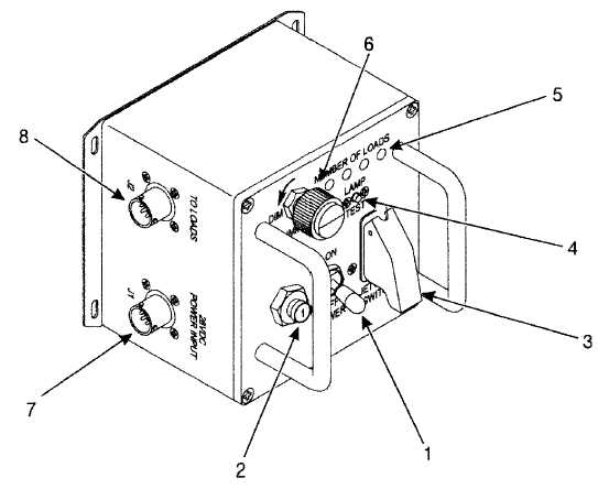
Control Box. The control box contains a power switch (1), and circuit breaker (2), a jettison switch (3), a
lamp test switch (4), four blue LEDs (5), a dimmer adjust knob (6), a power input connector (7), and a
connector (8) to the loads.
The POWER switch has a locking-lever to prevent it from being accidentally switched ON/OFF. The lock is
released by pulling the switch handle out while moving the handle to either position. The switch should
remain in the OFF position until the system is installed and ready for testing or use. Before switching the
power ON, confirm that the JETTISON SWITCH is OFF to prevent the squibs from firing.
The circuit breaker is an aircraft type, 1-amp, trip-free, push-pull. The JETTISON SWITCH is guarded to
prevent accidental firing of the squibs installed in the system. When the JETTISON SWITCH is activated,
all the squibs installed in the system will fire, thus releasing all the extraction lines from their system.
The LAMP TEST switch, when pressed, will illuminate the four blue LEDs on the control box when the
system is installed and powered ON. The blue LEDs, when lit, only indicate the quantity of loads installed,
not their location. If one load is installed, the left-most LED will illuminate. If two loads are installed, the two
left-most LEDs will illuminate. If the quantity of illuminated LEDs does not match the quantity of loads
installed, the LED on the Y-connectors should be observed to determine which load is not installed
correctly.
The DIMMER adjust knot controls the brightness of the LEDs on the control and on the Y-connectors.
Rotate the knob clockwise to increase the brightness, counter-clockwise to decrease the brightness. The
cover of the control box may be rotated in relation to the two cable connectors depending on mission.


