
TM 10-1670-327-23&P
0005 00
2
1
3
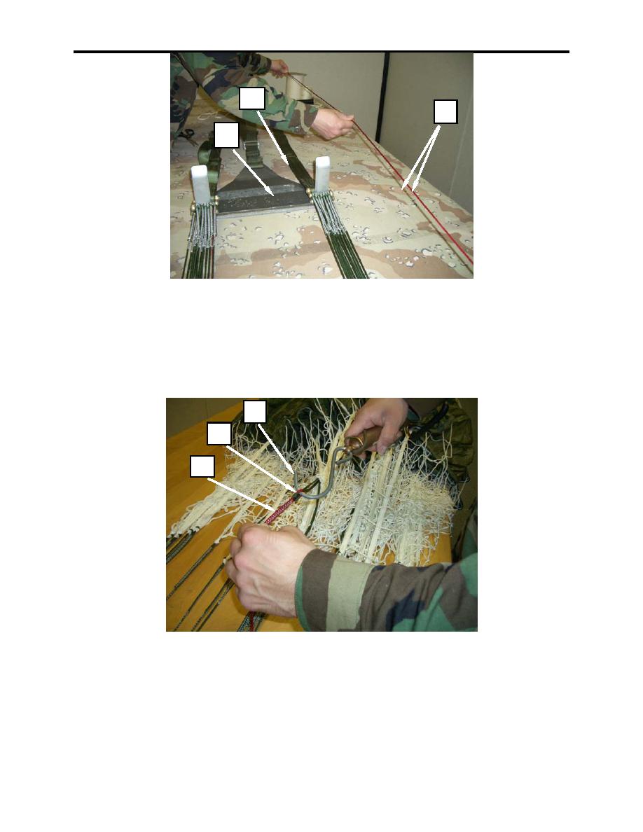
Figure 4. Tracing Lower Control Lines Down To Risers.
NOTE
Requires two rigger personnel to conduct measurement.
5. Measure the lower control lines (left and right) with 5 lbs of pressure.
6. Using a calibrated scale, insert the scale hook-end (figure 5, item 1) into the girth hitch (figure 5,
item 2) where the lower control line (figure 5, item 3) is attached to the middle control line cascade.
1
2
3
Figure 5. Inserting Scale Hook-end into Girth Hitch.
7. Measure from where the lower control line (figure 6, item 1) is girth hitched to the middle control line
cascade down to the riser end and mark the control line at 282 inches (figure 6, item 2) with a yellow
mark. Follow procedure for both lower control lines.
0005 00-4
