
TM 10-1670-327-23&P
0034 00
5. Replace the left or right forward control line assembly in this order:
a.
Middle Control Line Assembly
b.
Upper Long Control Line
c.
Upper Short Control Line
d.
Extended Gore Limiter Line
e.
Brake slot Control Line
f.
Lower Control Line
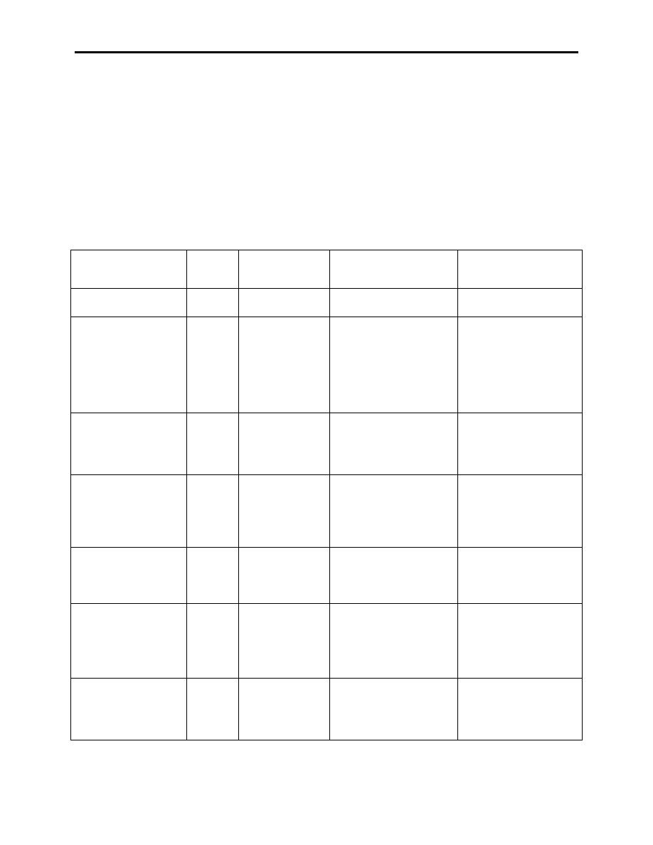
6. Use the following routing chart (Table 1) and layout illustrations left/right forward assemblies (figure
1,2) to assist with the proper installation of the new left/right forward control line assemblies.
7. Follow the procedures/steps for the control line being replaced as detailed in the appropriate section
of this work package.
Table 1. Control Line Routing Chart.
Line
Line
Connect From
Connect To
Routing
Nomenclature
Number
Lower Control Line
40
Middle Control
Riser Assembly
Line
Middle control Line
42
Guide Ring
Lower Control Line,
Girth Hitch to Guide
Connect Control Line
Ring, and free and
Limiter to Suspension
clear to Lower Control
Attaching Loop Line # 5
Line
Control Line Limiter
46
Guide Ring
Suspension Attaching
Girth Hitch to Guide
Loop Line # 5
Ring then to Control
Line Limiter Loop
Upper Control Line
43
1A Attaching
4A Attaching Loop
From Bottom to Top
Long
Loop
Through Ring
Upper Control Line
2A Attaching
3A Attaching Loop
From Bottom to Top
Short
44
Loop
Through Ring
Extended Gore Limit
Attaching Loop
Attaching Loop on
Route Under Upper
Line
48
on Gore # 5
Gore # 6
Control Line (Long)
Toggle
55
Lower Control Line
0034 00-2
