
TM 10-1670-327-23&P
0054 00
REPLACE - continued
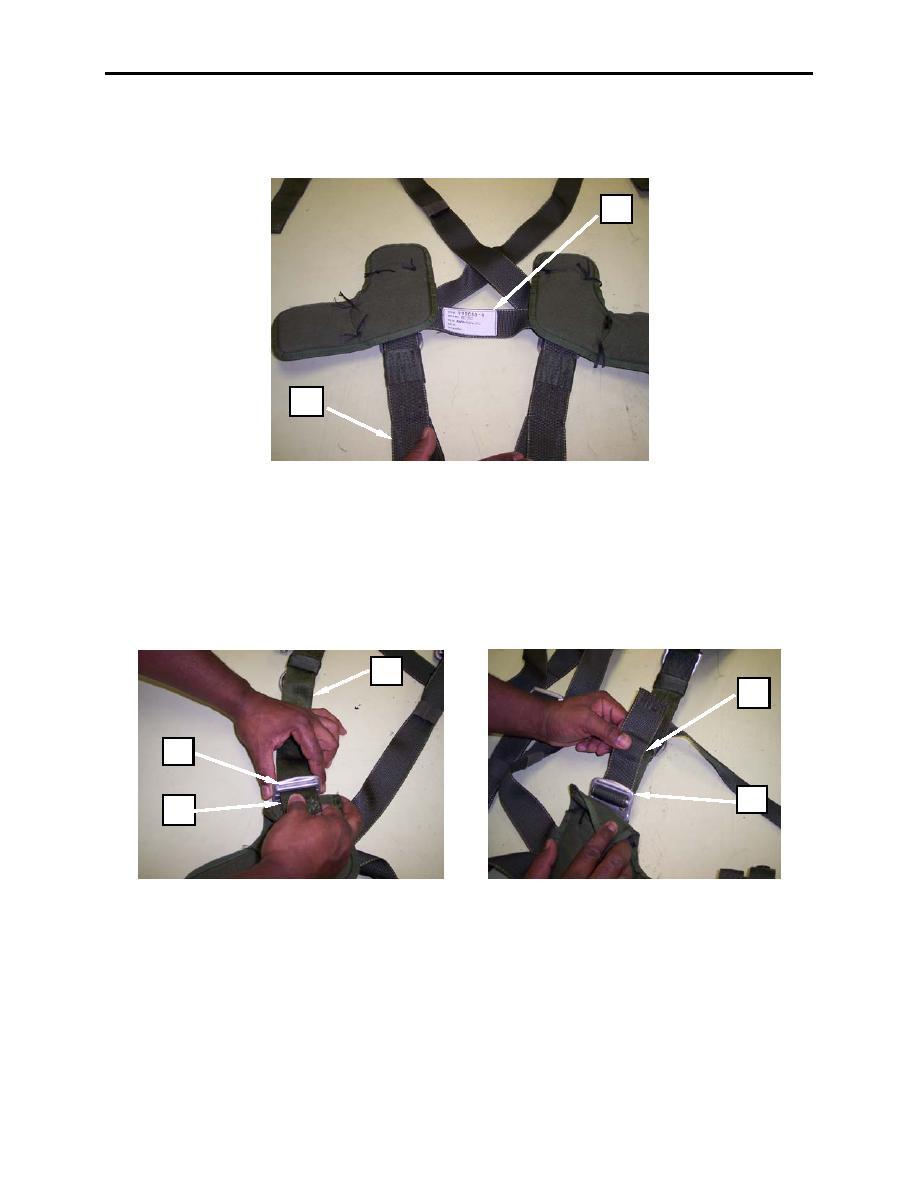
4. Layout the saddle assembly (figure 4, item 1) so that the horizontal backstrap data tag (figure 4,
item 2), and the ejector snaps are facing down.
2
1
Figure 4. Replacing the Saddle Assembly (continued).
5. To attach the new saddle assembly to the upper harness assembly (figure 5, item 1), route the upper
main lift web straps (figure 5, item 2) through the adjustment buckles (figure 5, item 3) route the
main lift web straps (figure 5, item 2) from top to bottom and then back up through the adjustment
buckle (figure 5, item 3).
6. Ensure that enough excess webbing is pulled through the saddle assembly adjustment buckle to
allow for sewing the tuck tab and snap fastener onto the left and right upper main lift web straps.
1
2
3
3
2
Figure 5. Replacing the Saddle Assembly (continued).
0054 00-3
