TM 10-1670-327-23&P
0072 00
REPLACE - continued
15. Top left suspension line group. Line 16 (outside top) followed in sequence by 17, 18, 19, 20 (inside
top) runs from the canopy, to the top right connector link.
Upper left
5 43 2 1
20 19 18 17 16
Upper right
o o o oo
o o o oo
Lower left
6 7 8 9 10
11 12 13 14 15
Lower right
o o o oo
o o o oo
Figure 5. Continuity Check.
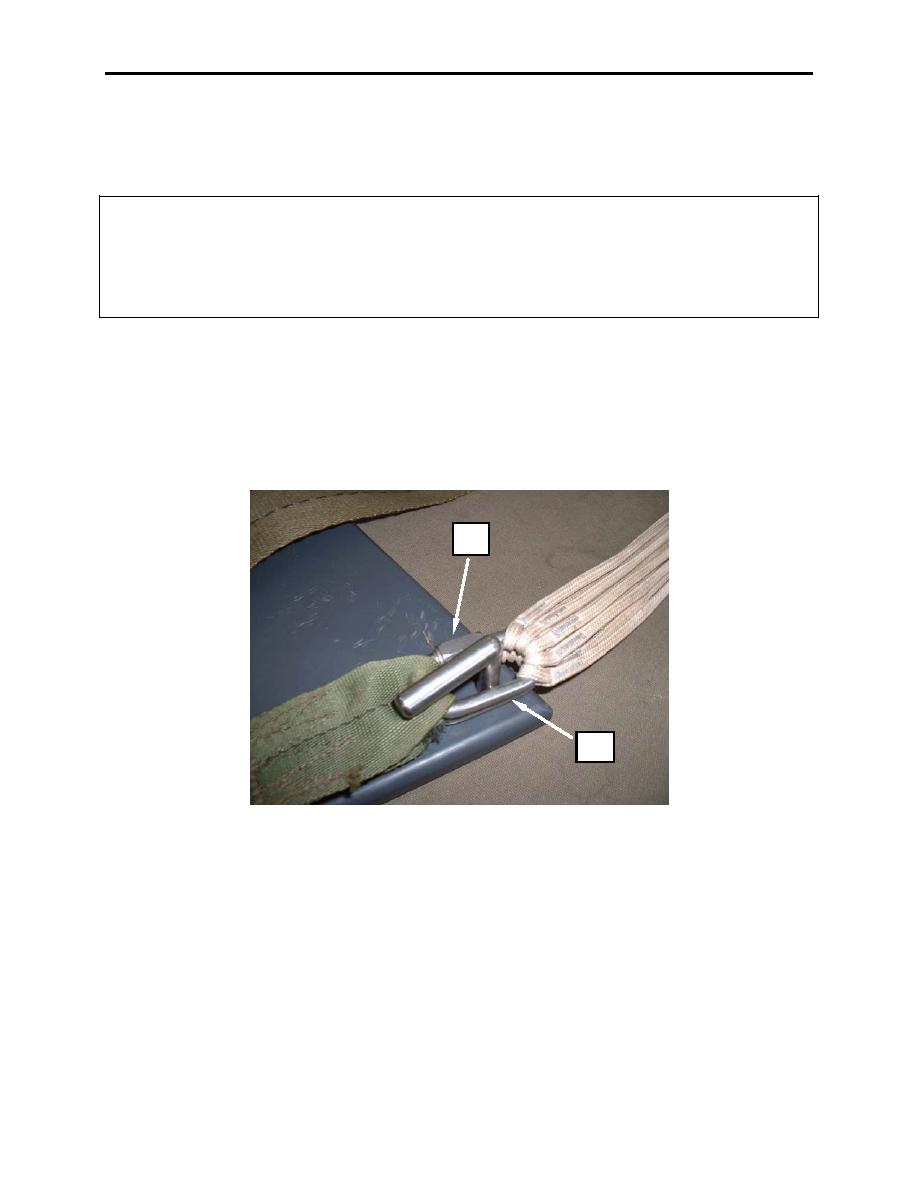
16. Using an 8-inch adjustable wrench, tighten barrel nut (figure 6, item 1) on connector links (figure 6,
item 2) until firmly seated against flange finger tight plus 1/4-turn.
17. Rotate each connector link (figure 6, item 2) sideways on the long portion of the connector link
(figure 6, item 2).
1
2
Figure 6. Tighten Barrel Nut On Connector Links.
18. Tack each riser (figure 7, item 1) with a 12-inch length of tape lacing (figure 7, item 2) and tying,
one turn double, passing the tacking needle (figure 7, item 3) tight against the body of the connector
link.
0072 00-5


