
TM 10-1670-327-23&P
0072 00
REPLACE - continued
NOTE
Connector link barrel nuts must be oriented so they face inboard and tighten downward.
NOTE
Suspension lines 1 thru 20 are divided into two groups, no. 1 thru 10 in the left group and
no. 11 thru 20 in the right group.
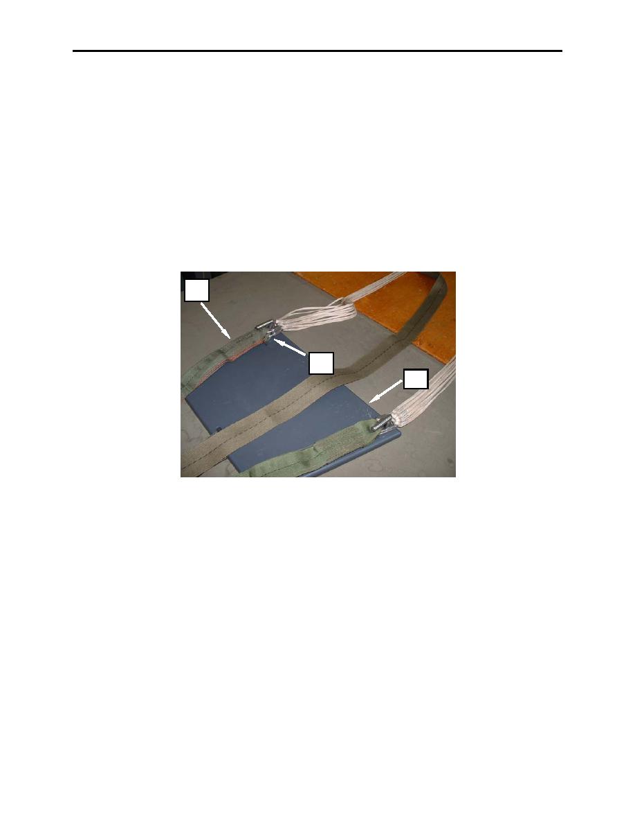
9. Attach the appropriate riser (figure 4, item 2) to the appropriate connector link (figure 4, item 1) (top
left connector link to the top left riser, etc).
10. Place the left set of connector links (figure 4, item 1) on the left post of the tension plate (figure 4,
item 3), and the right group of connector links on the right post of the tension plate (figure 4, item 3).
2
1
3
Figure 4. Attach Appropriate Riser to Appropriate Connector Link.
11. Conduct a continuity check as illustrated in Figure 5.
12. Top left suspension line group. Line 1 (inside top) followed in sequence by 2, 3, 4, 5 (outside top)
runs from the canopy, to the top left connector link.
13. Bottom left suspension line group. Line 6 (outside bottom) followed in sequence by 7, 8, 9, 10 (inside
bottom) runs from the canopy, to the bottom left connector link.
14. Bottom right suspension line group. Line 11 (inside bottom) followed in sequence by 12, 13, 14, 15
(outside bottom) runs from the canopy, to the bottom right connector link.
0072 00-4
