TM 10-1670-201-23
T.O. 13C-1-41
NAVAIR 13-1-17
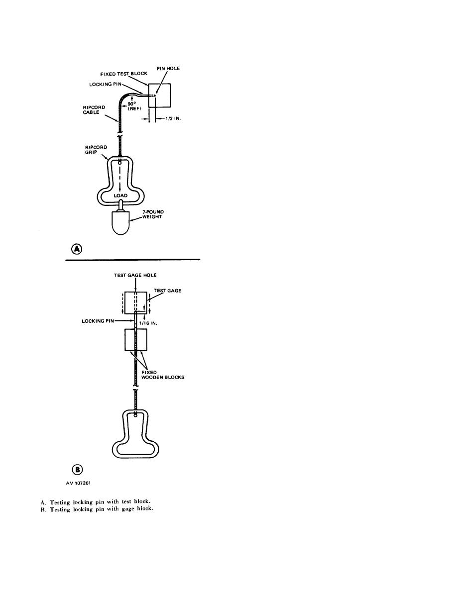
(b) Attach a 7-pound weight to the
ripcord grip handle and suspend the weight from the
handle, exercising care to apply the load gradually
without impact.
The hands or lifting device, as
applicable, must be fully removed from the weight.
NOTE
A ripcord locking pin will withstand a
7-pound load without assuming a
permanent set.
(c) Remove the weight, rotate the
locking pin one-quarter turn, and test the pin again by
reapplying the load as prescribed in (b) above.
(d) Repeat the procedure in (c) above
until the locking pin has been tested in four positions
and rotated one-quarter turn prior to each test.
NOTE
Each locking pin on a ripcord length
will be tested under load in four
positions.
(e) Remove the weight from the ripcord
grip and further remove the locking pin from the test
block.
(f) Visually examine the tested locking
pin to ascertain if it was marred, cracked, or distorted
during the test under load. If any defects are noted, the
ripcord will be removed from service.
(g) Repeat the procedures in (b)
through (f) above for the remaining locking pins on the
ripcord length. After testing all the locking pins, if there
are no visual defects apparent, each of the locking pins
will then be further tested for bends.
(h) Place a locking pin in a vertical
position with the pin end facing upward and either clamp
the pin between two wooden blocks at a point below the
pin shoulder (BI or hold between the thumb and index
finger of one hand.
(i) Using a test gage block, manually
locate the hole in the block over the end of the secured
pin, allowing for a 1 / 16-inch maximum insertion.
(j) With the axis of the gage block hole
alined with the axis of the locking pin, release the gage
block and allow the block to fall freely.
(k) When the weight of the gage block
fails to cause full penetration of the pin into the gage
block hole, the pin is excessively bent and ripcord will
be removed from service.
(I) Repeat the procedures in (h)
through (k) above for each of the remaining locking pins
on the ripcord length.
(2) Ripcord grip test. A ripcord which has
Figure 2-9. Performing a ripcord
satisfactorily completed the locking pin test in (1) above
locking pin test, typical.
will be further tested to ascertain that the ripcord grip
tubing joint is properly welded.
2-15


