ARMY TM 10-1670-276-23&P
AIR FORCE T.O. 13C5-29-2
NAVY NAVAIR 13-1-29
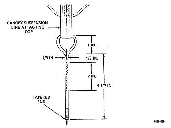
Figure 2-56. Securing Suspension Line at Suspension Line Attaching Loop.
(13) On the running end of the cord length, mark the cord at points 4 1/2, 7 1/2 and 12 inches from the tapered end
(figure 2-54).
(14) Trace replacement suspension line from canopy skirt down to applicable riser suspension line attaching loop.
(15) Apply tension to replacement suspension line equal to that of an adjacent suspension line to ascertain that marks
made on the replacement line are located correctly.
(16) Release tension on suspension line and attach line length to applicable riser suspension line attaching loop by
passing 6 3/4 inches of marked cord through original suspension line attaching loop on riser. Suspension lines shall be
attached to riser in numerical sequence (figure 2-57).
(17) Insert a suitable splicing aid to cord casing at the 12-inch mark and pass inserted aid down through the cord casing
and to outside at the 7-1/2-inch mark, in a manner similar to that shown in figure 2-55 but in the opposite direction.
(18) Insert cord tapered end into eye of splicing aid.
(19) Pull spicing aid and cord tapered end up inside cord casing until the 4 1/2- and 7 1/2-inch marks are alined.
(20) Hold alined marks together and pull splicing aid and cord tapered end up and to outside at 12-inch mark.
2-87