TM 10-1670-296-20&P 0043 00
0043 00-2
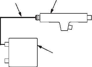
7. Install the 50-foot main cable (3) between the first Y-connector (2) and control box (4) (P1 connects to J1
on Y-connector; P2 connects to control box TO LOADS J2 connector).
CONTROL
BOX
Y-CONNECTOR
3
P2
P1
J3
J2
J1
J2
J1
4
2
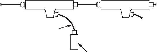
8. Retrieve and connect four platform cables (5) to initiator simulators (6) (P3 on platform cable connects to
J3 on Y-connector; P4 on platform cable connects to J1 on initiator simulator).
Y-CONNECTOR
Y-CONNECTOR
5
6
P4
J1
J1
J2
J2
J3
P3
J3
J1
NOTE
Ensure 28 VDC power supply is turned OFF and unplugged prior to
connecting to EPJS.
NOTE
Initiator simulators will be used in place of squibs to functionally test the
system. Each initiator simulator uses two 1-AMP circuit breakers to
simulator the dual bridge wire in the squib.