TM 10-1670-296-20&P 0043 00
0043 00-3
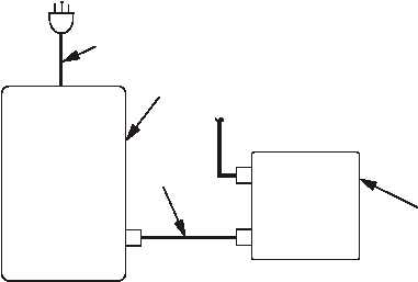
9. Install power cable (7) between control box (4) and 28 VDC power supply (8) (P1 connects to 28 VDC
power input J1; P2 connects to 28 VDC POWER SUPPLY).
CONTROL
BOX
28 VDC
POWER
SUPPLY
115 VAC
POWER
CABLE
7
P1
J2
J1
8
4
P2
TEST
1. Set control box POWER and JETTISON switches to OFF.
2. Ensure control box circuit breaker is set (pushed in).
3. Rotate DIMMER control to full on position.
4. Plug 28 VDC power supply into 115 VAC power.
5. Set all initiator simulator circuit breakers to ON.
6. Set 28 VDC POWER switch to ON.
7. Set control box POWER switch to ON. Verify that all four LEDs on control box are illuminated. Verify that
the LED on each Y-connector is illuminated. If conditions are not met, proceed to subsets a. through d. If
conditions are met, proceed to step 8.
a.
Verify LED is operable by pressing appropriate LAMP TEST switch.
b.
Verify cabling is properly connected.
c.
Verify initiator simulator circuit breakers are set to ON.
d.
If necessary, replace suspected initiator simulator, platform cable and/or Y-connector.
8. Set JETTISON SWITCH, on control box to JETTISON. Verify that all breakers on initiator simulators
have tripped (OFF position). If no breaker on any initiator trips, the control box is defective and must be
replaced. If the breaker(s) on only one initiator simulator does not trip, the associated Y-connector of the
initiator simulator is defective and must be replaced. Proceed as follows:


