ARMY TM 10-1670-275-23&P
AIR FORCE TO 13C5-25-2
NAVY NAVAIR 13-1-26
4706-064
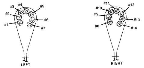
Figure 2-59. Suspension Line Numerical Sequence.
(17) Insert a suitable splicing aid to cord casing at the 11-inch mark and pass inserted aid down
through the cord casing and to outside at the 6-1/2-inch mark, in a manner similar to that shown in
figure 2-56, but in opposite direction.
(18) Insert cord tapered end into eye of splicing aid.
(19) Pull splicing aid and cord tapered end up inside cord casing until the 4 1/2- and 6 1/2-inch marks
are alined (see figure 2-57).
(20) Hold alined marks together and pull splicing aid and cord tapered end up and to outside at 11-inch
mark.
(21) Remove cord tapered end from splicing aid and while holding 112- and 6 1/2-inch marks together,
pull cord at a point above the 11-inch mark to allow cord tapered end to withdraw into cord casing.
(22) Beginning at a point 1/2 inch above alined 4 1/2- and 6 1/2-inch marks, using a zig-zag sewing
machine and size E nylon thread, secure formed loop by stitching a 118-inch wide, 2-inch long row of
stitching. Stitching will be 7 to 11 stitches per inch (see figure 2-60).
2-87