ARMY TM 10-1670-275-23&P
AIR FORCE TO 13C5-25-2
NAVY NAVAIR 13-1-26
2-31. Riser (cont).
(3) Restencil. As required, restencil identification marking using procedures in paragraph 2-19.
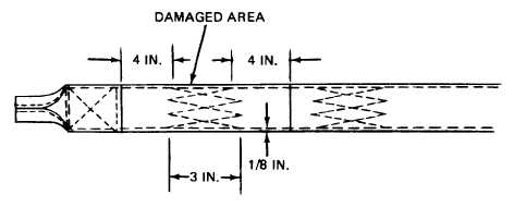
(4) Splicing. Each of the two riser straps may be spliced as follows:
NOTE
Each of two risers may be spliced one time.
(a) Cut a length of type VIII webbing long enough to extend 4 inches beyond each side of
damaged area and sear ends (para. 2-18).
(b) Center webbing length over damaged area (figure 2-62). Using a heavy duty sewing
machine and size 3 nylon thread, secure each end of splice by stitching a 3-inch long, three
point WW stitch formation, 1/8 inch in from each side edge of splice material. Overstitch
each end of splice material by one stitch on each point of stitch formation. Stitching shall be
5 to 8 stitches per inch.
4706-067
Figure 2-62. Riser Splicing Details.
b. Replacement. Replace an unserviceable riser by fabricating a replacement set as follows (refer to
figure 2-63):
NOTE
Prior to disconnecting the riser straps from the suspension lines, temporarily
secure each suspension line group to prevent disarrangement by passing a
suitable length of 1/4 inch cotton webbing through the loops on the lower end of the
suspension lines and tying the webbing ends together.
(1) If inspection data pocket (log record pocket) is serviceable, cut tacking which secures pocket to the
left riser strap and remove pocket. Retain pocket for use on riser which Is to be fabricated.
(2) Cut two 63-inch lengths of type VIII webbing and sear ends in accordance with paragraph 2-18.
2-90