TM 10-1670-327-23&P
0007 00
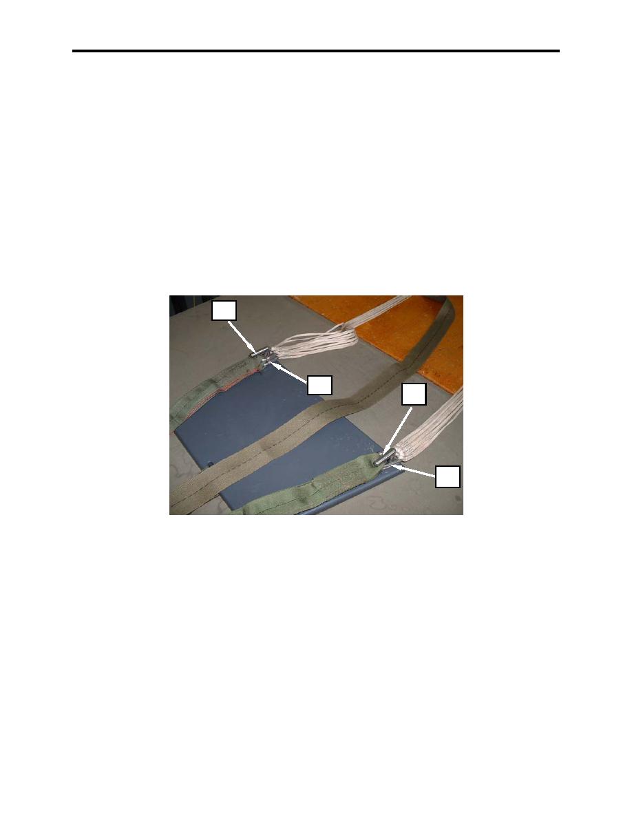
8. Using an 8-inch adjustable wrench, completely open the barrel nut on the connector links (figure 6,
item 1), remove connector links (figure 6, item 1) from line organizing card and loosely connect
connector links to proper riser (figure 6, item 2).
NOTE
Connector link barrel nuts must be oriented so they face inboard and tighten downward.
NOTE
Suspension lines 1 thru 20 are divided into two groups, no. 1 thru 10 in the left group and
no. 11 thru 20 in the right group.
9. Place the left set of connector links (figure 6, item 1) on the left post (figure 6, item 2) of the tension
plate and the right set of connector links (figure 6, item 3) on the right post (figure 6, item 4) of the
tension plate.
2
1
4
3
Figure 6. Riser Connector Links.
0007 00-5


