
TM 10-1670-327-23&P
0015 00
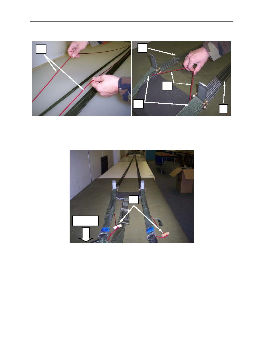
2. Trace the control lines (figure 31, item 1) down to the risers (figure 31, item 2) ensuring that left and
right control lines run inside of the suspension lines (figure 31, item 3) and are free and clear.
3
1
1
2
3
Figure 31. Tracing the Control Lines to the Risers.
3. Take slack out of control lines, by grasping the toggles (figure 32, item 1) and pulling control lines
towards the pack tray until all slack is pulled down to the riser end.
1
Pack Tray
Figure 32. Taking Slack from Control Lines.
4. Starting with the right riser group (figure 33, item 1) remove the connector link (figure 33, item 2)
from the tension bar, rotate the rear riser outward; this will orient the control line channels and guide
ring to the inside.
0015 00-24
