
TM 10-1670-327-23&P
0015 00
1
2
Figure 33. Rotate Riser and Reposition Connector Link on Tension Bar.
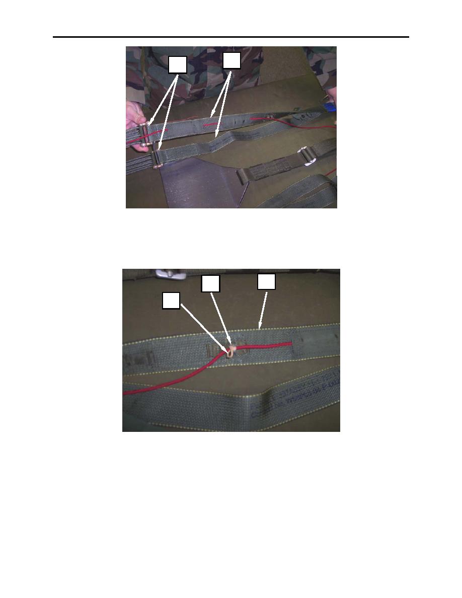
5. Attach a 1-1/16-inch retaining band (figure 34, item 1) onto the guide ring (figure 34, item 2) on the
right riser assembly (figure 34, item 3).
3
2
1
Figure 34. Attaching Retaining Band on Guide Ring of Right Riser Assembly.
6. Grasp the control line (figure 35, item 1) at the point between the guide ring (figure 35, item 2) and
control line channel (figure 35, item 3), pull the control line so that the toggle (figure 35, item 4) is
pulled tight up against the guide ring, then pull the remaining slack outwards.
0015 00-25
