
TM 10-1670-327-23&P
0029 00
REPLACE - continued
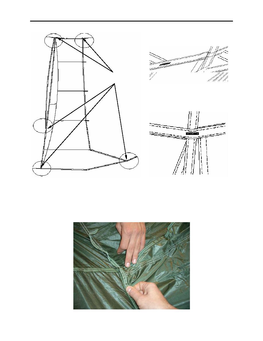
Bartack
locations
Figure 2. Brake slot opening of Extended Gore.
Figure 3. Bartack Intersections On Cross
Seam and Main Seam.
7. In the same manner as the original extended gore was positioned, align the forward upper corner of
the new extended gore with the forward upper inside corner of the open gore (figure 4) (on radial 8 or
21), laying the reinforcement tape on top of the canopy cross seam for at least 4 inches beyond the
extended gore with the end folded under a minimum of 1/4-inch on both ends.
Figure 4. Aligning New Extended Gore with Open Gore.
0029 00-3

