
TM 10-1670-327-23&P
0015 00
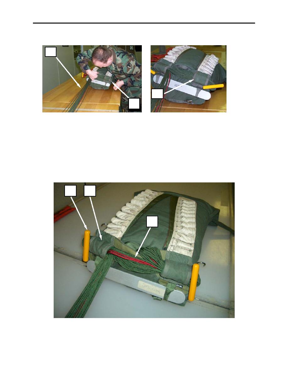
5. Pull the suspension line loop through the right locking stow loop (figure 47, item 3). Ends of stow
should extend 2 inches beyond locking stow loop.
1
3
2
Figure 47. Closing Deployment Bag and Stowing Suspension Lines (continued).
6. Grasp a section of the suspension lines (figure 48, item 1) approximately the width of the
deployment bag and form a second loop which extends 2 inches beyond the hood of left locking stow
loop.
7. Insert left stow hook (figure 48, item 2) through the formed suspension line loop. Ensuring that the
stow hook is around all of the suspension lines.
8. Pull the suspension line loop through the left locking stow loop (figure 48, item 3). Ends of the stow
should extend 2 inches beyond locking stow loop.
2
3
1
Figure 48. Closing Deployment Bag and Stowing Suspension Lines (continued).
0015 00-32
