
TM 10-1670-327-23&P
0015 00
Tying Connector Links and Suspension Line Protective Cover
1. Cover suspension lines with the suspension line protector cover.
NOTE
Make certain that riser groups are still in proper layout and control lines are routed to the
inside of the connector links.
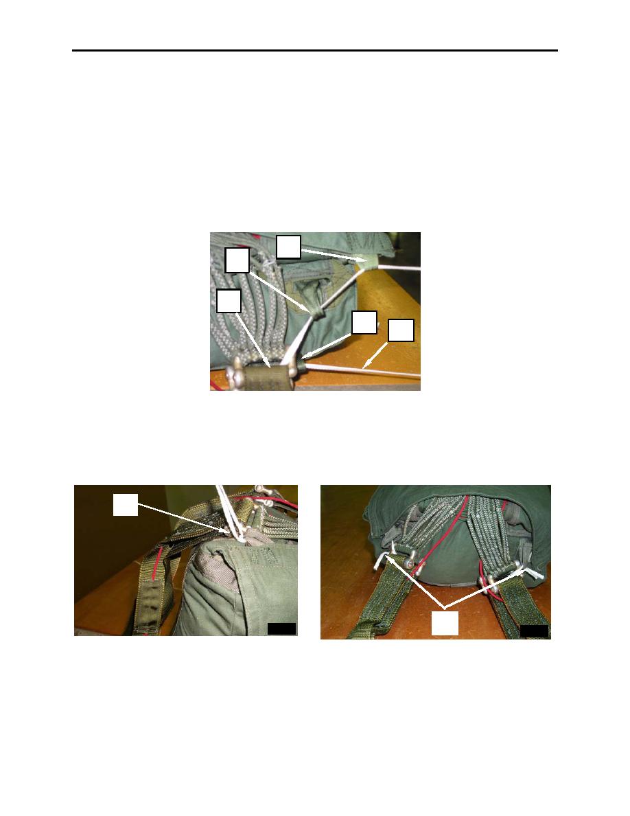
2. Using one-turn, single, 14-inch length of Type I, 1/4-inch cotton webbing (figure 53, item 1), pass an
end through the right bottom connector link tie loop (figure 53, item 2), through right pair of connector
links (figure 53, item 3), up through the top right connector link tie loop (figure 53, item 4), and
through suspension line protector cover tie loop (figure 53, item 5).
5
4
3
2
1
Figure 53. Tying Connector Links and Suspension Line Protective Cover.
3. Secure ends with a surgeon's knot and a locking knot (figure 54, item 1). Cut excess webbing,
leaving end approximately 2 inches long (figure 54, item 2).
4. Secure the left tie loops and connector links using procedures in step 2 and 3 above.
1
2
Figure 54. Tying Connector Links and Suspension Line Protective Cover (continued).
5. Enter deployment bag number into the log record book and sign as packer.
6. Rigger Check number 5.
0015 00-36
